Dustduino MCU Project (PROTO version)
-
Dustduino PROTO — 4-bit Microcontroller (First Version)
This is my project that I made to learn the basics of using Powder Toy elements to build logic gates and circuits. This is the very first version of the Dustduino family of microcontrollers, and I plan to make other versions and improve on this foundation. This version is a prototype, and has very limited features.
Stats:
- Registers: 2 (REG1 and REG2)
- ALU Operations: AND, XOR, OR
- Architecture: 4-bit
- Clock Frequency: 3Hz @ 60FPS
- Memory: 420 bits (~98 instructions)
- Pins:
- GPI (General Purpose Input)
- GPO (General Purpose Output)
- SIP (Special Input Pins - directly wired to main data bus)
- SOP (Special Output Pins)
- VCC+ (Power)
- INIT (Initializes newly created program memory)
- EXEC. (Fires when opcode is executed)
- INST. (Outputs freshly fetched instruction)
TPT saves:
- Dustduino Proto MCU: 3232370View Save 3232370
- MCU-Programmer: 3232371View Save 3232371
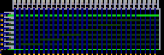
Instruction Memory:
Program for this MCU is divided into 14 blocks with 7 operations each. Each block is loaded into a FILT pixel, which holds 30 bits of data: 28 bits for 7 opcodes and 2 bits for IDC (Instruction Direction Control).
IDC Bits:
The IDC bits control where the first value (opcode) in the block is sent:
Bits Destination Description 00 IMUX Default — Instruction goes to Instruction Multiplexer 01 Databus Instruction value is sent directly to data bus 10 SOP Instruction value is sent to Special Output Pins Opcodes:
Decimal Mnemonic Description 0 CALCOR Calculate OR, clear buffers, send result to data bus 1 RIP Read from input pin buffer to data bus (clears buffer) 2 CALCAND Calculate AND, clear buffers, send result to data bus 3 TANDB Toggle gate for buffer B of AND module 4 TANDA Toggle gate for buffer A of AND module 5 TOP Toggle gate to output pins buffer (release on close) 6 TOR Toggle OR module gate to/from the data bus 7 CALCXOR Calculate XOR, clear buffers, send result to data bus 8 TXORB Toggle gate for buffer B of XOR module 9 TXORA Toggle gate for buffer A of XOR module 10 TREG1 Toggle gate to Reg 1 write pins 11 TREG2 Toggle gate to Reg 2 write pins 12 CREG2 Clear Reg 2 13 CREG1 Clear Reg 1 14 RREG1 Release value from Reg 1 to data bus 15 RREG2 Release value from Reg 2 to data bus Besically you just shape the path, where you want your data to go, by closing or opening right gates. E.g. If you want to transfer data from register 1 to AND-A buffer you might do it like this:
- Open Reg1 gate (TREG1)
- Write something there by putting data into databus. (e.g. RIP)
- Close Reg1 gate (TREG1) (to prevent other data mixing in)
- Open AND-A buffer (TANDA)
- Write data there by reading the register (RREG1)
- And closign the gate back (TANDA)
How to Program It:
- Open the MCU-Programmer save.
- Click the button for your desired opcode.
- Set IDC bits (only for the first instruction in a block).
- Use the green buttons:
- D-A: Sets IDC to 01 (Databus)
- D-B: Sets IDC to 10 (SOP)
- D-A + D-B: Sends to SOP (not intended)

- Click "Enter" to add the instruction and move to the next.
NOTE: If you finished writing and you're near the end of a block, and there's still space, just press Enter a few times until 2 SWCH indicators light up (finishing the block). This ensures that the block is finalized and written to the program. Like this:
Saving Your Program:
Once you're done writing the program, click the brown button labeled "R" to move the piston away from your program (cyan colored line). You can now copy it or save it to stamps.

How to load the program into microcontroller:
If microcontroller was already used, make sure that 2 counters in MCU look like that:
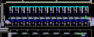
(All right-most SWCH must be on. If not, connect the MCU to the power supply and wait until they are. On the main save of the microcontroller, they will stay in that position.) This is needed to make sure that your program, once loaded, starts executing from the first block.
- Find the cyan line of memory in the microcontroller.
- Remove it.
- Paste your own line in that place. Make sure that FILT pixels (they are colored with darker cyan than INSL) are directly above the FRME of pistons below it.
- After placing your program, send a single pulse through the INIT pins. This will load the first block of your program into the counter by lifting the FILT pixel up and shooting BRAY through it. The top counter will change its position.
- Done. To start executing your program, connect the microcontroller to the power supply.
Future Plans
I am planning to make another version of the microcontroller—Dustduino Alpha, where I will entirely switch from INST to FILT. It will have better Data Flow Control in the main data bus, and I plan to use tristate buffers for that, as they are also used in the real world.
For instruction and memory systems, I aim to redesign things so the instruction set becomes more flexible, enabling the storing and loading of any value into memory. I’ll likely design a RAM module for it and give it a tighter connection with the main data bus.
The ALU and registers will be completely redesigned using FILT logic. Because of this, the clock speed may increase too.
After Dustduino Alpha, I will implement the Dustduino Core version. This too will use FILT technology and will build upon Alpha’s foundation for easier optimization. Core will include more registers and a more advanced ALU. This will be the foundational platform for the more advanced versions of my microcontroller family.
Edited 9 times by UAGoose. Last: 20th Apr 2025 -
Will the more advanced ALU have arithmetic operations?
-
Yes. This is the list of things I want to implement in Dustduino Core ALU:
- Adder (you may also subtract with it)
- Shift Left/Right operations
- basic bitwise operations (AND, OR, XOR, NOT)
- Comparison flags (equal, more, less)
Values might be also signed. But I am not sure on this one.
Edited 2 times by UAGoose. Last: 24th Apr 2025 -
RIP :sob:
The adder will be fun, i promise. /j
Anyway, it's just the thing, it's either a small slow adder, or a fast adder where it's fairly hard to make it small enough. I'm building a filt computer right now and still can't figure out how to build one in. Tho it's not really of high priority to make it small.
A serial adder calculated every bit at once, by having hardware for every one of them, so it's big.
A sequential adder has hardware only for one bit and just repeats the process 30 times, so it's slow, like 2 seconds for a 15 bit number.
id:2998545 is a simple example of a fast, serial one. Good luck suffering the same way as me.
Edited 2 times by resic. Last: 25th Apr 2025 -
Yeah, I already have some issues with addition logic in Alpha version. I am making an incrementor for program counter that would feed last value into itself (I made it in this way for easier JUMP logic and conditionals). I made it as usual with carry logic and it takes like a frame for each bit +other minor delays. I thought that would be simple circuit but it is not.
So I will try designing faster adder with reasonable size (and suffer along side... RIP my sanity). I am currently reserching CLA, CSA and KSA types of adders.
Thank you for pointing this out and providing useful information. Any other suggestions are welcomed and appreciated.
Edited 4 times by UAGoose. Last: 25th Apr 2025


